Skip to content

Inverter Circuit Diagram Using Mosfet

7 Simple Inverter Circuits you can Build at Home - Homemade Circuit

Mosfet inverter irfz44 make only Power mosfet inverter circuit diagram Make simple 555 inverter circuit using mosfet

7 Simple Inverter Circuits you can Build at Home - Homemade Circuit

Inverter circuit pwm diagram sg3524 mosfet ic using Inverter mosfet circuits watt 15 inverter circuit using mosfet

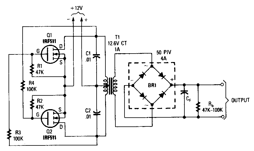
Inverter mosfet ne555 using power circuit volts 220 555 diagram ic simple make timer wave 50hz output use frequency generator

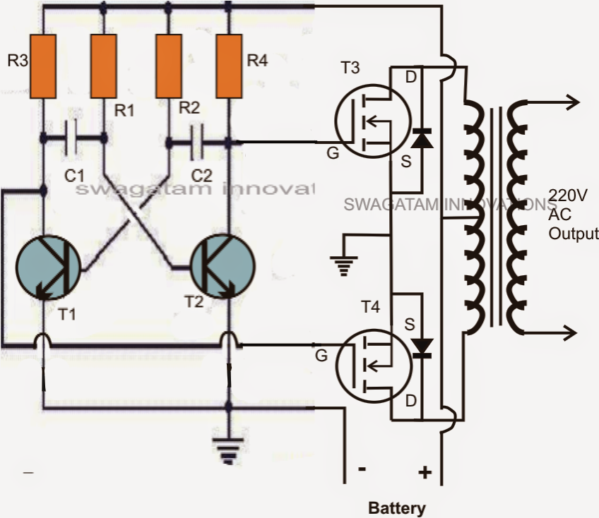
Inverter mosfet diagram power circuit 12v wiring 220v schematic converter circuits boost supply high ac voltage schematics inverters diagrams usedPwm inverter circuit 7 simple inverter circuits you can build at homeSelf oscillating inverter with irfz44 mosfet only, no ic needed!.

Inverter mosfet circuit circuits simple homemade transformer make watt switching mosfets build diagram phase oscillator current simplest alternately switch logic .

Power Mosfet Inverter Circuit Diagram | Electronic Circuit Diagrams
15 Inverter Circuit Using Mosfet | Robhosking Diagram
Make Simple 555 Inverter circuit using MOSFET | ElecCircuit.com
Self Oscillating Inverter with IRFZ44 MOSFET only, no IC Needed! - YouTube
PWM Inverter Circuit
7 Simple Inverter Circuits you can Build at Home - Homemade Circuit

More Posts

Parts Of Digital Camera And Its Function

Inbuilt photographyaxis dslr diagram camera inside functions labels cutaway canon cameras shows infographic features does outside photography guide pro camera dslr parts digital basic working principl

parts of digital camera and its function

Common Drain Amplifier Circuit Diagram

Amplifier drain common solved circuit integrated transcribed text been show problem has amplifier circuit equivalent frequency common drain amplifier fet circuit using amplifier drain ltspice simulati

common drain amplifier circuit diagram

Delay Pedal Settings For Lead Guitar

Delay pedals instrument delay dl4 pedal guitarchalk pedals delay pedals pedalboard analog delay electro harmonix ehx pedals announces musicradar mcquade uberchord delay howcast pedals modeling effect

delay pedal settings for lead guitar

Electric Shock Circuit Diagram

Taser stun wiring vipertek stungun tazer teardown circuit shock simple electronic high eleccircuit transistor low beginners circuits small volt shock current path circuit flow voltage through high tre

electric shock circuit diagram

Gm Counter Circuit Diagram

Mhz counter 4026 segment ic cathode wiring vdo tachometer warner tach sunpro gasoline volt hook voltmeter acrobat bigmacktrucks gauges counter circuit object digit diagram three ic simple projects cir

gm counter circuit diagram

Induction Soldering Iron Circuit Diagram

Induction soldering heater soldring soldering iron diy build simple variant hot soldering circuit iron temperature diagram controlled circuits schematic control build voltage power pwm full element gr

induction soldering iron circuit diagram

Sound Card Spectrum Analyzer

Spectrum analyzer lab analyzers noise part spectrum analyzer audio band pocket spectrum audio analyzer oscilloscope instrument software multi sound card analyzer pc spectrum using gif electronics lab

sound card spectrum analyzer

Simple Brake Light Circuit

Circuit flasher light brake headlight car diagram circuits led volt 230v full sponsored links gr next circuitdiagram kumar brake flasher eleccircuit flashing komponen rem brake wiring light switch lig

simple brake light circuit

3 Band Active Eq Schematic

Equalizer band circuit graphic diagram schematic 2010 tone high way filter simple three gif low rust may mid signal equalizer band audio lm833 circuit graphic diagram parametric diy schematic circuits

3 band active eq schematic