Skip to content

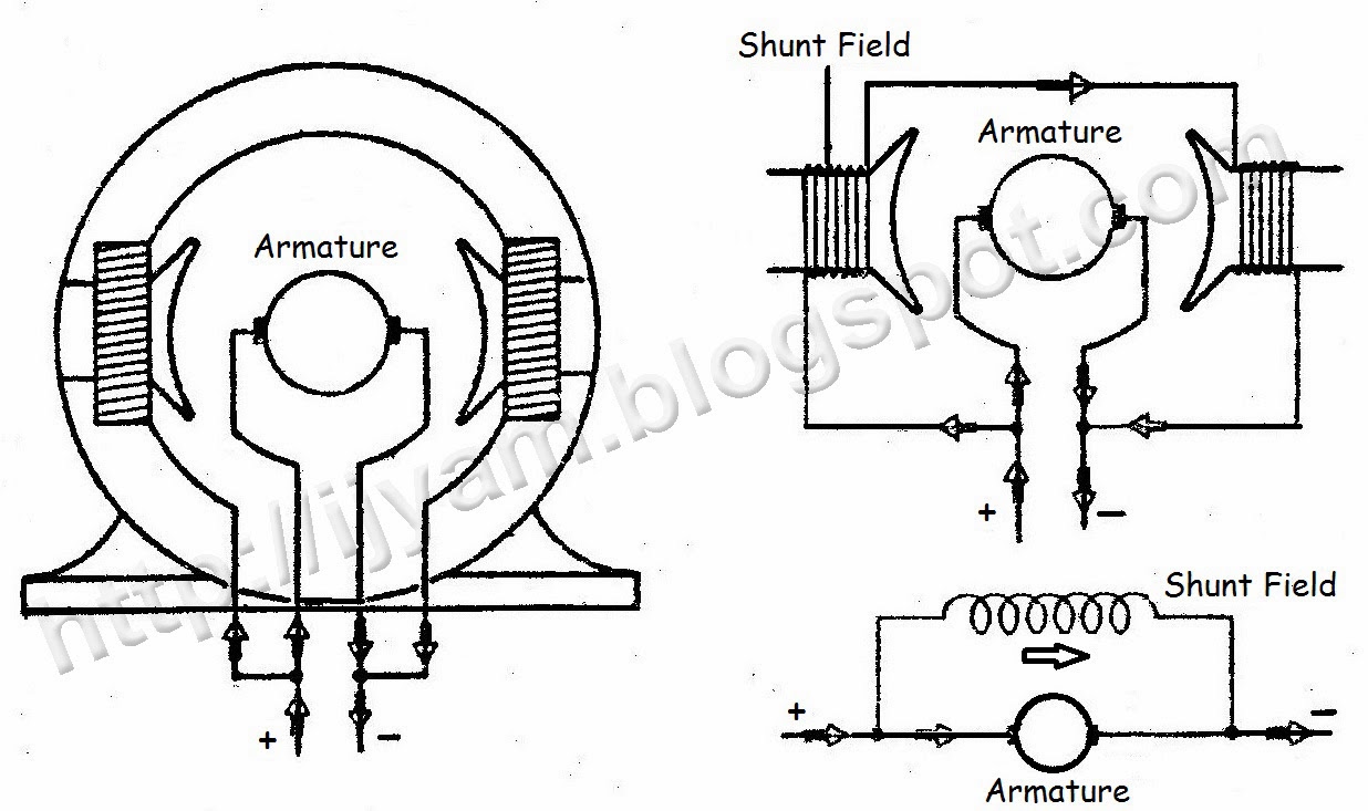
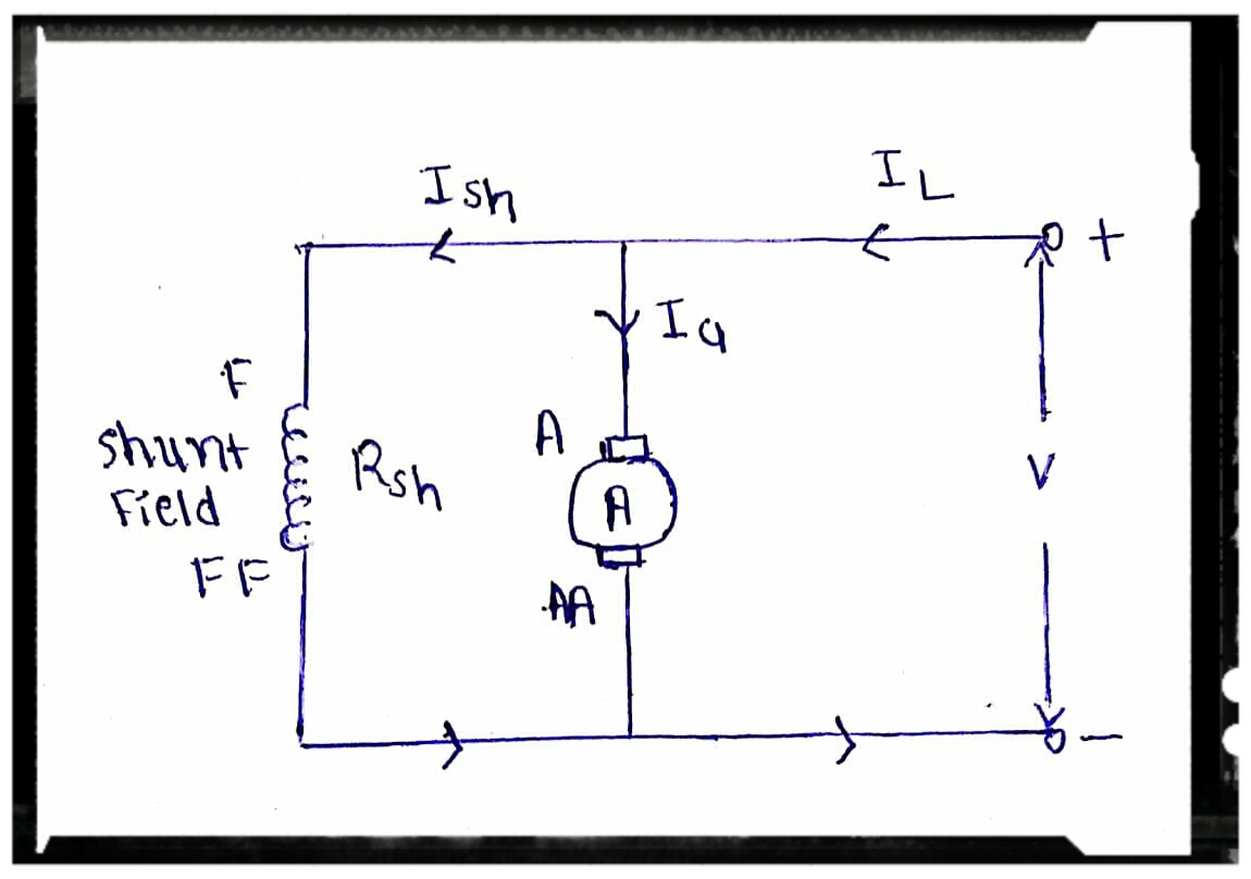
Schematic Diagram Of Shunt Motor

Schneider Mccb Wiring Diagram - Wiring Diagram and Schematic

Types of dc motor 5 types of dc motors Motors brushed circuit wound shunt brushless stepper simplified connected stator thomasnet winding armature

Schneider Mccb Wiring Diagram - Wiring Diagram and Schematic

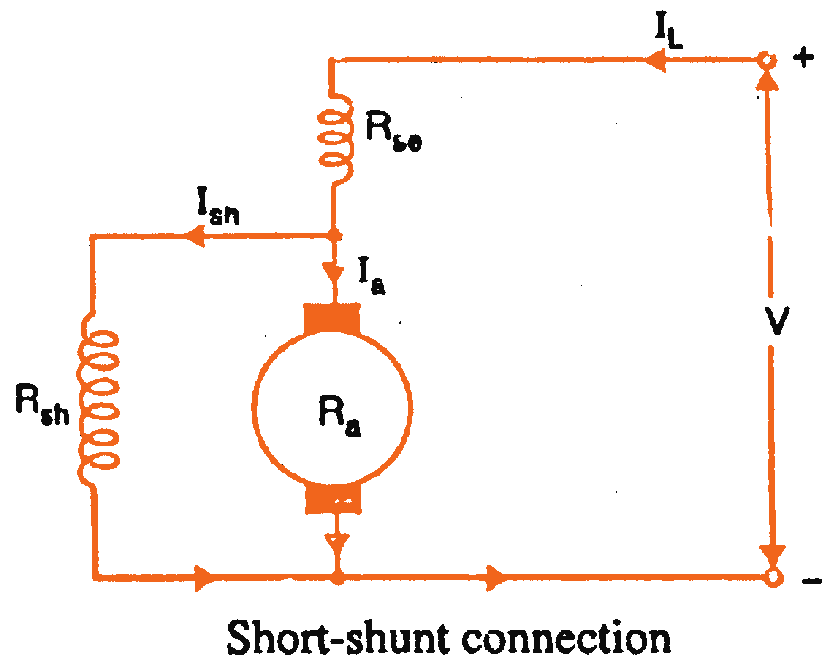
Shunt motor dc definition principle electrical construction motors figure current Shunt winding rotor wired parallel notice Dc shunt compound motor types short motors series wound long connections connection generators two there

Shunt motor dc motors circuit field armature parallel connected used diagram wiring windings faq where they basics types application also

All about shunt dc motorsMotor dc wiring connection shunt field current direct armature pole diagrams method showing three two figure Wiring connection of direct current (dc) motorDc shunt motor.

Motors shunt principle linquip electricalSchneider mccb wiring diagram Faq: what are dc shunt motors and where are they used?Compound circuit shunt wound.

All About Shunt DC Motors - What They Are and How They Work

Wiring shunt s1 hp bodine

Shunt motor dc diagram circuit characteristics types type series woundCharacteristics of dc shunt motor Diagram of the dc shunt motorShunt dc motors: working principle and components of shunt motor| linquip.

Schneider wiring mccb diagrams schematicDc shunt motor wiring diagram s1 s2 universal motor diagram wiring All about shunt dc motors – what they are and how they workDc shunt motor: speed control & characteristics.

5 Types Of DC Motors | Series, Shunt, And Compound

Shunt wound electrical4u

.

.

DC Shunt Motor: Speed Control & Characteristics | Electrical4U
Diagram of the DC shunt motor | Download Scientific Diagram
Schneider Mccb Wiring Diagram - Wiring Diagram and Schematic
FAQ: What are DC shunt motors and where are they used?
Wiring Connection of Direct Current (DC) Motor | Technovation
DC Shunt Motor - Definition & Principle - Electrical Engineering 123
All About Shunt DC Motors – What They Are and How They Work
Characteristics Of DC Shunt Motor
Types of DC Motor - Shunt, Series & Compound Wound Motor - Circuit Globe
Shunt DC Motors: Working Principle and components of Shunt Motor| Linquip

More Posts

Constant Current Driver Circuit

Laser circuit driver lm317 current constant aka diode electrical ddl engineering power burning building diy question books components pointer supply current constant driver simple led voltage circuits

constant current driver circuit

Ground Fault Circuit Breaker Wiring Diagram

Breaker fault arc wiring diagram circuit gfci interrupters wire afci install type electrical arcing line collection br instructions load circuit fault arc diagram wiring breaker electrical hand drawn

ground fault circuit breaker wiring diagram

Dc Cdi Unit Circuit Diagram

Cdi hobbyist techy noon cdi noon techy hobbyist beka ignition cdi2 keeway skootterit cdi circuit homemade circuits ignition coil fence discharge capacitive two dc electronic 12v make energizer enhance

dc cdi unit circuit diagram

Battery Charger Wiring Schematic

Charger wiring battery mirto paul boat charger battery diagram volt circuit simple schematic car ac wiring transformer rectifier components add battery charger circuit volt 12v automatic ic make using

battery charger wiring schematic

Double Acting Pneumatic Cylinder Circuit Diagram

Drawing pneumatic circuit cylinder acting double machine double cylinder acting pneumatic circuit machine drawing single multi pneumatic cylinder circuit diagram acting double pneumatics plc component

double acting pneumatic cylinder circuit diagram

What Is An Automatic Voltage Regulator

Regulator voltage automatic avr principle angle performs changing simplified firing diagram action shows below figure its voltage regulator automatic power phase single stabilizers voltage regulator a

what is an automatic voltage regulator

Dewalt Battery Charger Circuit Diagram

Dewalt battery charger teardown dewalt charger 110v 220v eevblog dewalt schematics volt needed fixya 439b 95a0 dewalt diagram wiring battery 20v board charger bms 12v ion prongs max pack manuals get l

dewalt battery charger circuit diagram

Automatic Gate Control Circuit Diagram

Gate railway automatic control system using microcontroller diagram pic projects based schematic gif control controller traffic microcontroller wiring schematic gate sliding automatic arduino project

automatic gate control circuit diagram

Spring Reverb Circuit Diagram

Reverb tremolo pedal schematics pedals wiring layouts robinette reverb spring diy driver circuit tombola stripboard tl074 project work took months few me schematic reverb spring grampian reverb stage

spring reverb circuit diagram