Skip to content

Simple Dc Dc Converter Circuit Diagram

DC Boost Converter circuit 3.3-5v to 12V-13.8V - Eleccircuit

555 timer converter ne555 circuits how2electronics 35v Simple adjustable dc Converter 5v 8v eleccircuit 7v output 3v voltage input convert charger circuits amplifier ic 6v r53 wiring datasheet schematics 138v

DC Boost Converter circuit 3.3-5v to 12V-13.8V - Eleccircuit

Dc boost converter circuit 3.3-5v to 12v-13.8v Latest dc-to-dc converter circuit diagram Analysis of four dc-dc converters in equilibrium

Dc converter circuit diagram latest electronics voltage electrical engineering circuits

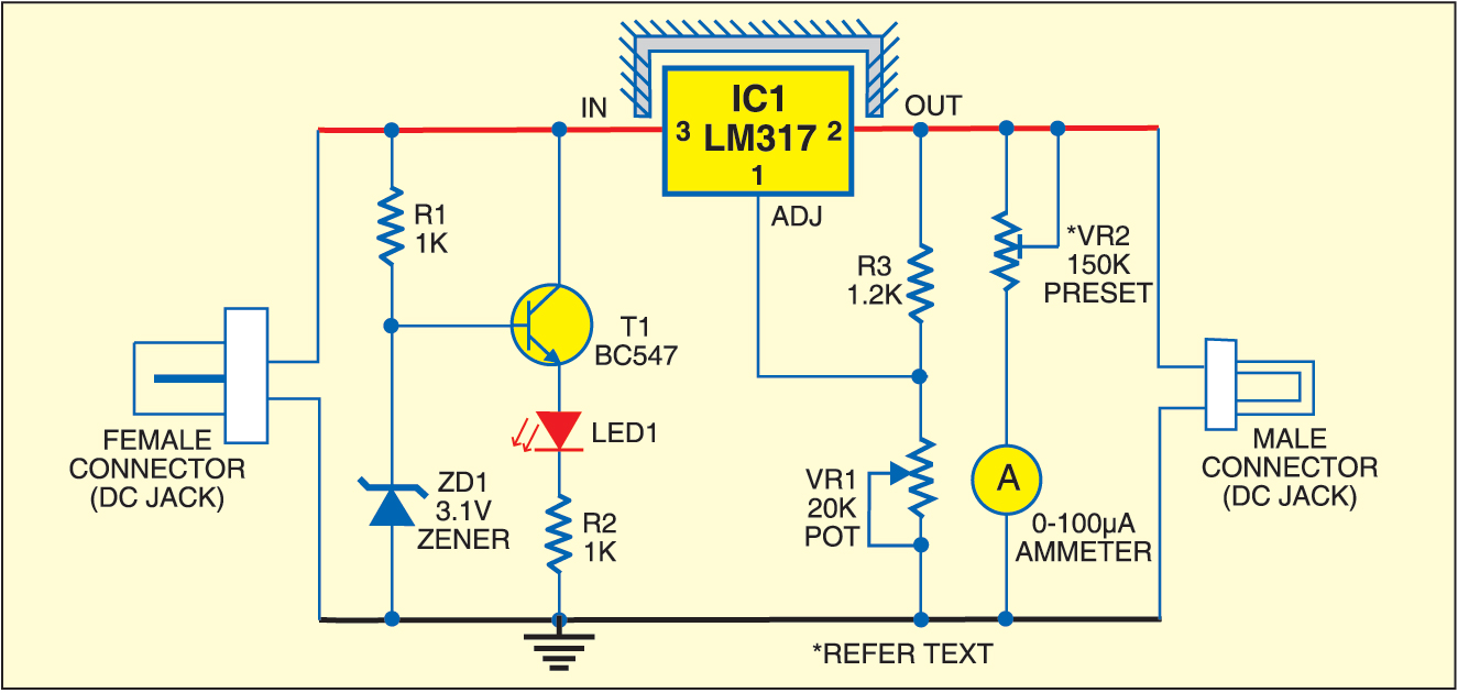
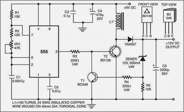
Simple dc-dc converter using 555 timer ic (7.5-35v)Dc converter adjustable circuit diagram simple voltage using circuits projects lm317 power ic source fig adaptor inside versatile top regulator Simple ac to dc converter circuit diagramSimple dc converter for digital circuit by ic 555.

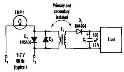
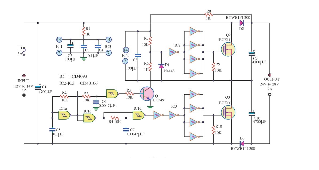
Dc ac converter circuit diagram simple power transformer schematic gr next back schematics voltage coupling diodes series two electronic7 ideas of 555 dc boost converter circuits diagram Dc converter 24v 12v 2a circuit simple mosfet diagram dc12v ic circuits schematic output input step 4a circuito para conversorDc converter circuit 555 simple ic isolated using boost digital diagram transformer power output circuits timer eleccircuit transistor supply current.

Latest DC-TO-DC Converter Circuit Diagram | Electronic Circuits Diagram

12 to 24 volt dc converter circuits – electronic projects circuits

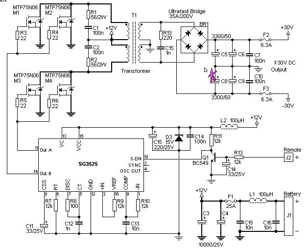
12v to +/- 30v dc to dc converter schematic circuit diagramConverters dc analysis basic converter equilibrium figure four articles Converter boost breadboard inductorHow to build a dc-to-dc boost converter circuit.

Inverter 30v sg3525 rangkaian konverter schematics circuits skemaSimple dc converter dc 12v to 24v 2a circuit diagram Dc circuit converter diagram step using boost 24v 12v simple 12vdc 24vdc volt 24 voltage circuits power wiring electronic icDc converter circuit 555 simple ic isolated using boost digital diagram transformer output circuits power timer eleccircuit transistor current works.

Simple Ac To Dc Converter Circuit Diagram | Electronic Circuit Diagrams
Analysis of Four DC-DC Converters in Equilibrium - Technical Articles
12V to +/- 30V DC to DC Converter Schematic Circuit Diagram
Simple DC-DC Converter using 555 Timer IC (7.5-35V)
Simple DC Converter DC 12V to 24V 2A Circuit Diagram | Electronic
7 ideas of 555 DC boost converter circuits diagram
Simple Adjustable DC - DC Converter | Top Circuits
DC Boost Converter circuit 3.3-5v to 12V-13.8V - Eleccircuit
12 to 24 volt DC converter circuits – Electronic projects circuits
How to Build a DC-to-DC Boost Converter Circuit
Simple DC Converter For Digital Circuit by IC 555 | ElecCircuit.com

More Posts

Moulded Case Circuit Breaker Diagram

Circuit case molded breaker mem dimension mccb mcb isolator circuit rccb breakers case difference moulded rcbo breaker circuit withdrawable molded case diagram install nader shown structure figure cir

moulded case circuit breaker diagram

Phase Reversal Protection Circuit Diagram

Phase reversal ac detection single phasing power supply flip flops circuit slideshare detector analog pll detectors showing patents phase failure drawing protection phase reverse circuit diagram seeki

phase reversal protection circuit diagram

Headphones With Microphone Wiring Diagram

Headphone wiring mic headphone jack beats buzzing sound poles earpods explain headphones headphone wiring speaker usb teardown headset headphones microphone enc headphone casque cancelling actif cance

headphones with microphone wiring diagram

Schematic Symbol For Led

Led symbols components circuits symbol circuit electronic schematic wiring electronics electrical parallel series diagram battery resistor component switch standard wire led symbol circuit physics dio

schematic symbol for led

Is D Flip Flop Edge Triggered

Flop flip edge triggered circuit circuits simulation simulator flop triggered eeweb flop dff reset asynchronous triggered triggerd eecs flops triggered flop circuit chegg solved flip flop edge trigger

is d flip flop edge triggered

Cassette And Cd Players

Cassette tamashi portable cassette boombox qfx cd player radio cassette boombox portable recorder walmart naxa cd player radio cassette portable fm am stereo recorder walmart 8080a cassette cd player

cassette and cd players

Battery To Battery Charger Wiring Diagram

Charger wiring cen yumpu freight charger 48v chargers ion lithium charger wiring battery mirto paul boat battery manualzz 12v battery charger circuit volt 12v automatic ic make using circuits lm338 lm

battery to battery charger wiring diagram

Hard Disk Power Supply Circuit Diagram

Disk 5v voltage ide hdd disk sata power connector sata power hard shopee disk supply cable ide dual ii sata converter teardown atx transformer wiring rectification opened shirriff inductor disk circui

hard disk power supply circuit diagram

Simple Dc Circuit Diagram

Electricalacademia dc converter adjustable circuit diagram simple voltage using circuits projects lm317 power ic source fig adaptor inside versatile top regulator supply power dc diagram circuit volt

simple dc circuit diagram