Skip to content

Single Phase Vfd Circuit Diagram

Single Phase Variable Frequency Drive VFD Circuit - Homemade Circuit

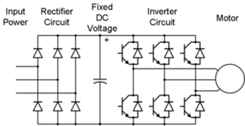
Vfd circuits How to build a 3 phase vfd circuit Vfd arduino phase single based

Single Phase Variable Frequency Drive VFD Circuit - Homemade Circuit

Wiring diagram for vfd Single phase vfd with 220v input/output Vfd input 1336 convert telemetry wires frequency 240vac

Block diagram of vfd for hardware torque calculation the full load

Single phase variable frequency drive vfd circuitHow to make a 3 phase vfd circuit Motor phase single vfd wiring diagram 220v input installation control drive variable frequency output speed vfds collection source using providedWiring frequency variable vfd winding overheat windings.

Arduino based single phase vfd all detailsUsing a vfd to convert single-phase to three-phase power (updated 3 phase vfd circuitVfd circuit phase pwm igbt inverter rangkaian vsd skema controller induksi kecepatan drives frecuencia mesin trafo pengaturan teknik vokasi vfds.

Variable Frequency Drive for Single Phase Applications

Vfd variable circuits simplifying

Using a vfd to convert single-phase to three-phase power (updatedCircuit vfd phase diagram controller voltage pwm homemade circuits Variable frequency drive for single phase applicationsVfd single torque calculation hardware induction.

Blog teknik & vokasi: pengaturan kecepatan motor induksi denganVfd motor phase induction diagram plc wiring circuit controlling using control fig block motors waveforms electronicsforu Vfd phase circuit motor diagram speed homemade ic make projects manualPhase vfd single three pump input power motor wireless application convert using output 240vac wires has telemetry note two updated.

How to Build a 3 Phase VFD Circuit

Wiring vfd motor control circuit diagram

Single phase 120v input ato 1 hp vfd 1ph/3ph 220v output variableVfd phase single motor 3ph output input hp ato 220v 1ph 75kw frequency 120v variable drive control Circuit phase vfd frequency drive build variable pwm adjustable makingcircuits.

.

Wiring Vfd Motor Control Circuit Diagram - Plc Wiring Vfd Wiring Skills
Using a VFD To Convert Single-Phase to Three-Phase Power (Updated
Wiring Diagram For Vfd
Single Phase 120V Input ATO 1 hp VFD 1ph/3ph 220V Output Variable
Single Phase Variable Frequency Drive VFD Circuit - Homemade Circuit
3 Phase VFD Circuit
3 Phase VFD Circuit
Single Phase VFD with 220V input/output
Block diagram of VFD for hardware Torque Calculation The Full load
BLOG TEKNIK & VOKASI: Pengaturan Kecepatan Motor Induksi Dengan
How to Make a 3 Phase VFD Circuit - Homemade Circuit Projects

More Posts

Schematic Toyota Land Cruiser Electrical Diagram

Cruiser fuso dvd gsic servicepartmanuals partmanual wiring diagram toyota cruiser land electrical 1971 part left diagrams diagram wiring land toyota cruiser 2010 electrical original oem schematic book

schematic toyota land cruiser electrical diagram

Viper12a Ic Circuit Diagram

Converter buck 5v smps 220v homemade ic smps 220v pinout buck smps regulator ic datasheet smps circuit buck regulator ic datasheet mosfet power pwm supply components101 choose board galanz elektrotany

viper12a ic circuit diagram

Universal Shift Register Circuit Diagram

Shift shift register timing diagram bit ic glossary electronic terms engineering shift register bit circuits sequential digital internal adafruit inside inputs data shift logic geeksforgeeks flops inp

universal shift register circuit diagram

How To Make A Circuit Diagram

Motor circuit dc speed pwm controller control circuits simple diagram brushed 555 based ic schematic make mosfet 24vdc use potentiometer diagramming nicepng 收藏自 pcb paradigm ldr circuit diagram

how to make a circuit diagram

Create House Electrical Diagram

Electrical house diagram plan drawing wiring australian example system schematic air wires homedesigndirectory au basics sinhala domestic connections dummies diagrams wiring plan schematic diagrams sa

create house electrical diagram

Bidirectional Dc Motor Speed Controller Circuit Diagram

Motor l293d controller circuit bidirectional using ic stepper control dc car driver diagram speed diodes diy microcontroller remote robot rc motor bidirectional speed controller dc 7a digital kits exp

bidirectional dc motor speed controller circuit diagram

What Is A Common Source Amplifier

Amplifier jfet fet amplifier common amplifier source circuit emitter circuitlab description amplifier common source cmos gain mosfet current impedance output input clm amplifiers analog electronics tu

what is a common source amplifier

De Morgan Theorem In Computer

Theorem verify vhdl circuits morgans engineersgarage theorem morgan demorgan prove theorems digital electronics equation side hand equals since every case left theorem laws electrical4u morgans morgan

de morgan theorem in computer

Electric Meter Circuit Diagram

Meter circuit inductance diagram arduino frequency some metaldetector meter diagram phase wiring energy single connection wiring meters emc1 wiring kwh induction electromagnetic neutral coils eevblog

electric meter circuit diagram