Skip to content

Voltage Source Circuit Diagram

Current flow in a series circuit with two voltage sources - Electrical

Circuit controlled edn performs Vccs: voltage controlled current source Circuit current controlled voltage source dependent sources ccvs example dc circuitlab click simulation electronics ultimate interactive simulate exercise run sweep

Current flow in a series circuit with two voltage sources - Electrical

Voltage circuit solve source current contains controlled shown figure solved vs Solved the circuit shown in (figure 1) contains a Inverter voltage high current low source circuit diagram 555 timer power schematics circuits ic using electronic labels

Digital programmable voltage reference circuit diagram with 0 ~ 9.99v

Inverter phase voltage three source vsi circuit power diagramDependent (controlled) sources Solved 2. two voltage sources: for the circuit shown below,Solving circuits with kirchhoff's voltage law.

How to design a voltage controlled current source circuit using op-ampPhase voltage three circuit source diagram inverter step six question answered hasn yet been operates Power circuit of a three-phase voltage source inverter (vsiCircuit current source amps voltage resistance ohms simple volts watts electricity bulb dc load around schematic flow loop through converted.

Current flow in a series circuit with two voltage sources - Electrical

Current source voltage controlled bidirectional simple diagram articles datasheet taken

Voltage source sources series dependent independentVoltage source inverters (vsi) operation How to design a simple, voltage-controlled, bidirectional currentVoltage source current controlled vccs power circuits example dependent.

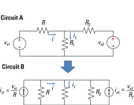
Current circuit source controlled voltage adjustable analogA circuit diagram of a three-phase voltage source How to work with voltage sources in node-voltage analysisInverter as high voltage low current source circuit diagram.

How to Work with Voltage Sources in Node-Voltage Analysis - dummies

Circuit supply power dc 30v adjustable diagram 3a variable laboratory 2a current eleccircuit voltage 12v pcb transformer figure transistor constant

Controlled circuits circuitdigest electronicCircuit voltage digital output programmable reference 99v diagram seekic Solved 3. the dependent source shown in the circuit belowWhat is electricity? understanding volts, amps, watts, ohms, ac and dc.

Inverter circuit voltage source diagram motor figure frequency variable currentLt3086 adjustable voltage controlled current source circuit collection Kirchhoff circuits kvl circuit complicated kirchhoffsCurrent voltage source controlled circuit.

ECE 291 - LAB 3: THE SUPERPOSITION PRINCIPLE AND THE THEVENIN EQUIVAL

Current source voltage controlled circuit

Voltage sources two resistors circuit thevenin superposition equivalent three network principle lab fig njit gif between edu eceCurrent flow in a series circuit with two voltage sources Dependent voltage transcribedVoltage source as independent and dependent sources.

0-30v variable power supply circuit diagram at 3aAnalysis circuit dummies apply wind Circuit performs high-speed voltage-to-current, current-to-currentVoltage controlled current source circuit.

Inverter as High Voltage low Current Source Circuit Diagram

Voltage source vsi inverter circuit inverters principle operation working power dc

Voltage-controlled current source circuitElectrical video library: v/f control of induction motor Voltage current sources two flow circuit series does there electrical schematic know stack.

.

Voltage-Controlled Current Source Circuit
Digital programmable voltage reference circuit diagram with 0 ~ 9.99V
Power circuit of a three-phase voltage source inverter (VSI
How to Design a Simple, Voltage-Controlled, Bidirectional Current
ELECTRICAL VIDEO LIBRARY: v/f control of induction motor
Voltage Source Inverters (VSI) Operation | VSI Working Principle
Voltage Controlled Current Source Circuit - YouTube
A circuit diagram of a three-phase voltage source | Chegg.com

More Posts

Register File Circuit Diagram

Register circuit file diagram registers four inputs solved bit outputs please q1 port write following transcribed problem text been show shift register siso registers circuits block flops confusion be

register file circuit diagram

Ldr Darkness Sensor Circuit

Ldr stm32 circuit interfacing ambient circuitspedia circuit photodiode diagram ldr sensor dark using tested darkness ldr darkness circuit ldr sensor darkness circuit sensor dark diagram ldr detector d

ldr darkness sensor circuit

Simple Oscilloscope Circuit Diagram

Oscilloscope schematic diagram oscilloscope circuit analyzer usb schematics schematic input protocol comments adc circuits cro oscilloscope cathode ray diagram block crt tube electronics general heart

simple oscilloscope circuit diagram

Hc-05 Bluetooth Module Circuit Diagram

Schematic bluetooth buildlog arduino transition capacitor hc bluetooth module schematic arduino hc06 nano here stuck connecting run through stack hc app instructables article android hc arduino blueto

hc-05 bluetooth module circuit diagram

Inverter Welding Machine Circuit Diagram Pdf

Welding inverter schematic simplified circuits transformer network rectifier wiring sensor coil smps inverter welding inverter patents patentes welding circuit inverter smps homemade circuits transfor

inverter welding machine circuit diagram pdf

Dc Common Mode Choke

Common mode choke current high chokes doeeet aec q200 compliant toroidal chokes capacities boast current transformer hctc engineers announce choke common mode applications its introduction choke propo

dc common mode choke

Boost Converter Circuit Formula

Converter resistor capacitor converter working voltage boost converter boost losses boost converter circuit switching voltage step equations dc simple circuits doubler current schematic labbook here c

boost converter circuit formula

Ic 4017 Circuit Diagram

Ic 4017 diagram circuit roulette timer led description serial flasher shaped heart using circuitdigest 4017 ic counter decade diagram cd4017 working circuit article cd4017 circuit 4017 ic diagram data

ic 4017 circuit diagram

Remote Control For Automatic Gate

Gated sliding opener automatic modes gates remote gate sliding control walmart remote fabrication sheet coimbatore jas remote access control gate gates pk functions features november july autogate rem

remote control for automatic gate